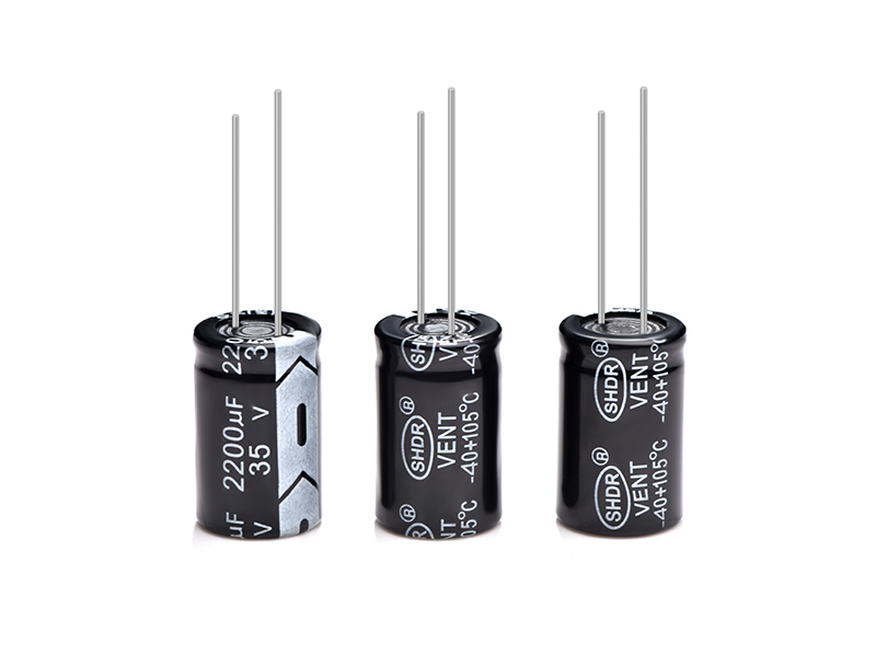
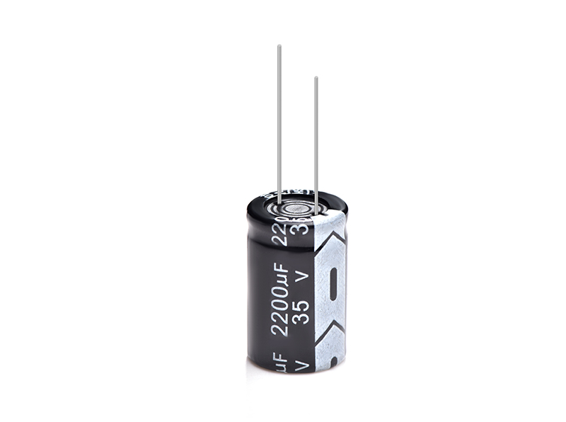
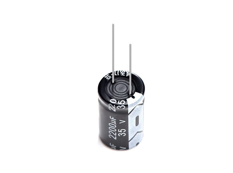
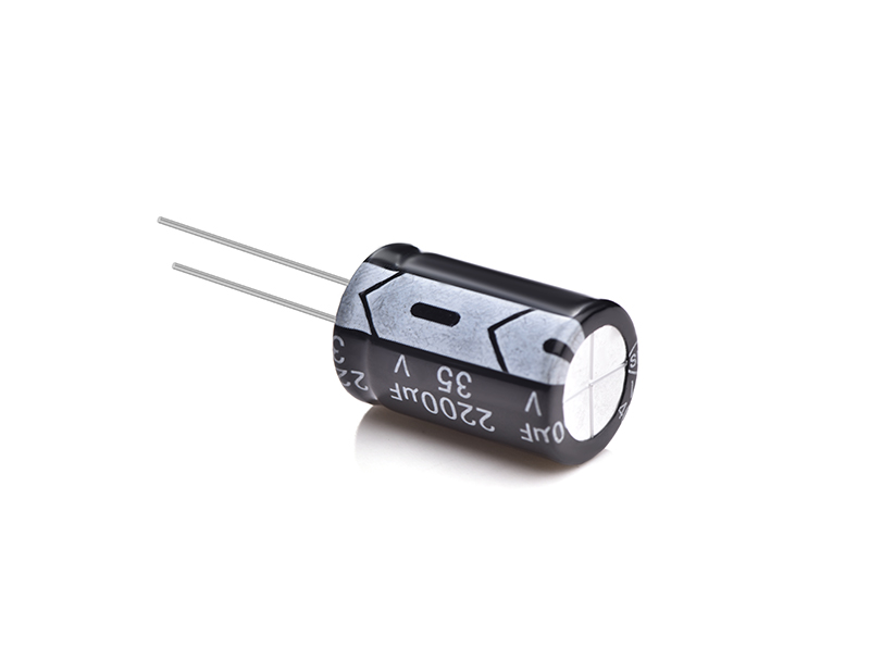
Electrolytic capacitor 2200UF35V
SHDR® Application Notes
Designing Device Circuits
1. Select capacitors suitable for installation and operating conditions,
and use capacitors to meet specified performance limits
this catalog or product specification.
2. Polarity
Aluminum electrolytic capacitors are polarized.
Do not apply reverse voltage or AC voltage to polarized capacitors.
Using reversed polarity can cause short circuit or venting. before use,
Refer to catalog, product specification or capacitor body to identify
Polarity marking. (The shape of the rubber seal does not represent
Polarity direction rules. ) use bipolar non-solid aluminum
Electrolytic Capacitors for Circuits Where Polarity Occurs
reverse. However, be aware that even bipolar aluminum electrolytic
Capacitors must not be used in AC voltage applications.
3. Working voltage
Do not apply DC voltage exceeding the rated voltage. This
Peak voltage of AC voltage (ripple voltage) superimposed on DC
The voltage must not exceed the full rated voltage.
Surge voltage value above full rated voltage is specified
in the catalog, but this is a restricted condition, especially in the short term
time.
4. Ripple current
Ripple current ratings are specified at a certain ripple frequency.
The rated ripple current at several frequencies must be calculated by
Use the original frequency to multiply the rated ripple current
Frequency multipliers for each product family.
5. Category temperature
Using Capacitors Outside the Maximum Rating Category Temperature
Will greatly shorten the life or cause the capacitor to vent.
The relationship between life and life of aluminum electrolytic capacitors
The ambient temperature follows the Arrhenius law, that is, the lifetime is
The ambient temperature is approximately halved for every 10°C increase in ambient temperature.
6. Life expectancy
Capacitors are selected to suit the life of the device.
7. Charge and discharge
Do not use capacitors in circuits with high charge and discharge capacity
The cycle repeats frequently. frequent and violent re-discharge
Cycling will result in reduced capacitance and capacitor damage
due to the heat generated. Specified capacitors can be designed to last
such conditions. Fast charge/discharge can be repeated in the circuit
where the ripple voltage across the aluminum electrolysis
Capacitance fluctuates a lot. If the voltage variation range exceeds
70Vp-p, please consult us.
8. Failure Modes of Capacitors
Non-solid aluminum electrolytic capacitors generally have a lifespan
Ending with an open circuit, the cycle depends on the temperature.
Therefore, the life of the capacitor can be reduced by
Ambient temperature and/or ripple current
9. Insulation
a) Electrically isolate the following parts of the capacitor from the negative pole
terminals, positive terminals and circuit traces.
• Cases for non-solid aluminum electrolytic capacitors.
• Dummy terminals for non-solid aluminum electrolytic capacitors,
This is designed for installation stability.
b) The casing of the capacitor is not guaranteed to be an insulator (except
for screw type). For applications requiring an insulating outer layer
sleeve, custom designed capacitors are recommended.
10. Conditions
Do not use/exposed capacitors under the following conditions.
a) Oil, water, brine. Avoid storing in damp places.
b) Direct sunlight.
c) Toxic gases such as hydrogen sulfide, sulfurous acid, nitrous acid, chlorine or its compounds, and ammonium.
d) Ozone, UV or radiation.
e) Severe vibration or mechanical shock conditions beyond the limit
specified in the catalog or product specification.
11. Installation
a) Electrolytic paper and electrolytic conductive electrolyte
Non-solid aluminum electrolytic capacitors are flammable. leakage
Electrolyte on printed circuit boards can gradually corrode copper
traces, which may cause smoking or burning through a short circuit
copper traces.
Verify the following points when designing the PC board.
• Provide proper hole spacing on PC board to match
Terminal spacing of capacitors.
• Leave the following open space above the vent so that the vent can
Proper operation.
Case Diameter Clearance
Ø6.3 to Ø16mm minimum 2mm
Ø18 to Ø35mm minimum 3mm
Ø40mm or more 5mm minimum
• Do not place any wires or copper traces on the device's vents.
capacitor.
• Installing a capacitor with a vent facing the PC board requires a
There are proper ventilation holes on the PC board.
• Do not run any copper traces under the capacitor seal.
The traces must go through 1 or 2mm to one side of the capacitor.
• Avoid placing any hot objects near
capacitors, even on the reverse side of the PC board.
• Do not pass anything through holes or under capacitors.
• When designing double-sided printed circuit boards, do not place any copper
Trace the sealed side of the next capacitor.
b) Do not install the terminal side of the screw-mounted capacitor downward.
If the screw terminal capacitor is mounted on its side, make sure
Positive is higher than negative.
Do not fasten the terminal screws and mounting clips to the
Specified torque specified in catalog or product specification
Quote.
c) For surface mount capacitors, design the copper pads of the PC board
According to catalog or product specification.
12. Others
a) The electrical characteristics of capacitors vary with temperature, frequency and lifetime. By taking the design of the device circuit
Take these changes into account.
b) Capacitors installed in parallel require current to flow evenly
individual capacitors.
c) Capacitors installed in series need to be connected in parallel with resistors
Separate capacitors to balance the voltage.
d) Use capacitors in applications where safety is always a concern. to consult
Our factories are before they are used in applications that can affect human life. (space
equipment, aviation equipment, nuclear equipment, medical equipment,
vehicle control equipment, etc.) Please note that this product is
Designed for a specific purpose, not for other purposes
use. (eg photo flash type etc.)
Product Picture


Copyright © Guangzhou Shenghe Electronic Technology Co., Ltd. All Rights Reserved Sitemap | Powered by
