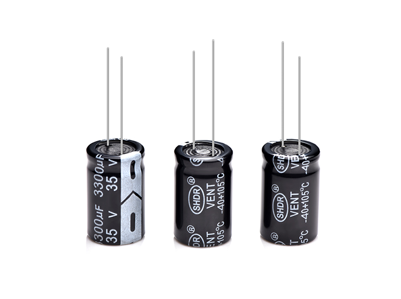
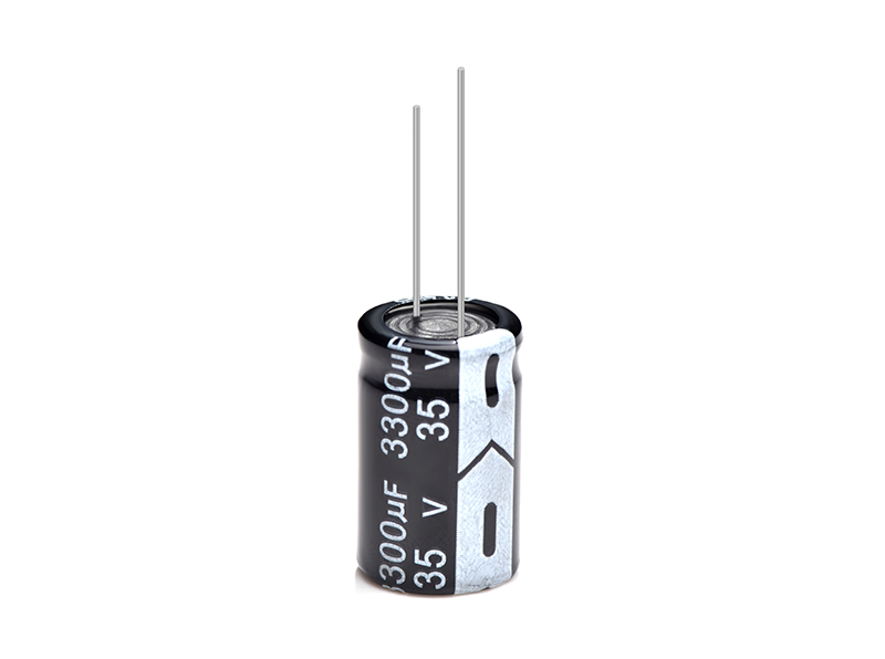
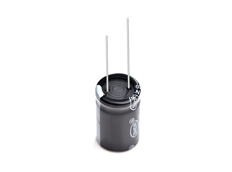
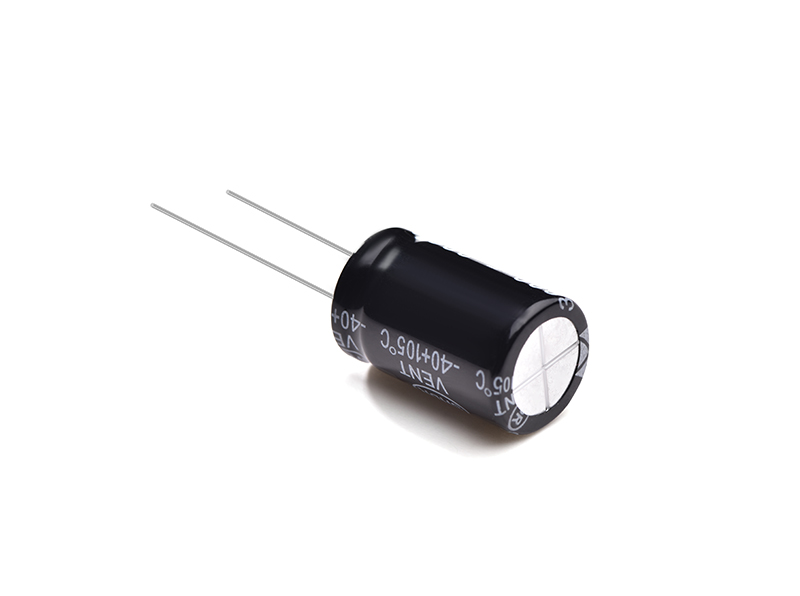
Aluminum Electrolytic Capacitor 3300uf35v
SHDR® Application Notes
■ Install capacitors
1. Installation
a) Used capacitors cannot be reused unless the capacitor
Remove from equipment for periodic inspection to measure its
electrical characteristics.
b) If the capacitor is self-charging, discharge the capacitor through a
Use a resistor of about 1kΩ before use.
c) If the capacitor is stored at 35°C or higher and exceeds
75% RH, leakage current may increase. In this case, they can re-
Formed by applying the rated voltage through a resistor of approximately
1kΩ.
d) Verify the rated capacity and voltage of the capacitors at the time of installation.
e) Verify the polarity of the capacitors.
f) Do not use the capacitor if it has been dropped on the floor.
g) Do not deform the case of the capacitor.
h) Verify that the lead spacing of the capacitor matches the hole spacing
Before installing the capacitors on the PC board. some standard pre-
Formed leads are available.
i) For pin terminals or snap-in terminals, insert the terminal into
PC board and press the capacitor down until the bottom
The capacitor body reaches the surface of the PC board.
j) Do not apply any mechanical force exceeding the specified limits
in the capacitor's catalog or product specification. return,
Note that capacitors may be damaged by mechanical shock caused by
Centering operations for vacuum/insertion heads, component checkers or automatic mounting or insertion machines.
2. Solderability and Solderability
a) When soldering with a soldering iron
• Soldering conditions (temperature and time) should be within limits
specified in the catalog or product specification.
• If the terminal spacing of the capacitor does not match the terminal hole spacing of the PC board, modify the terminals to minimize
Mechanical stress enters the body of the capacitor.
• Remove the capacitor from the printed circuit board, after the solder is completely
Melt, minimize mechanical rework by using a soldering iron
stress capacitors.
• Do not touch the capacitor body with the hot tip of the soldering iron.
b) Flow soldering
• Do not immerse the capacitor body in the solder pool, only the capacitor
Terminals are in. Soldering must be done on the reverse side of the PC
board.
• Soldering conditions (preheating, soldering temperature and immersion time)
should be within the scope specified in the catalog or product
Specification.
• Do not apply flux to any part other than the capacitor terminals.
• Make sure the capacitor does not touch any other
components while soldering.
c) Reflow soldering (SMD type only)
• Soldering conditions (preheating, soldering temperature and immersion time)
Should be within the range specified in the catalog or product specification
Quote.
• When setting the temperature infrared heater, consider
Infrared absorption causes material to discolor and change
appearance.
• Do not use reflow to solder capacitors multiple times. if it should be
Made it twice, please consult us first.
• Make sure the capacitors are not in contact with the copper traces.
d) Do not reuse surface mount capacitors that have been soldered.
Also, when installing new capacitors on the assembly board
Rework to remove old residual flux from PC board surfaces,
Then use the soldering iron under the specified conditions.
e) Confirm whether the capacitor is suitable for reflow soldering.
3. Treatment after welding
Do not apply any mechanical stress to the capacitor after soldering
motherboard.
a) Do not tilt or twist the body of the capacitor after soldering -
acitors to the PC board.
b) Do not use capacitors to lift or carry assembled boards.
c) Do not knock or poke the capacitors after they are soldered to the PC board.
When stacking assembled boards, be aware that other components will not
Do not touch aluminum electrolytic capacitors.
d) Do not drop the assembly board.
4. Clean the PC board
a) Do not use the following cleaning agents to clean capacitors.
• Halogenated Solvents: Causes capacitors to fail due to corrosion.
• Alkaline system solvents: Corrode (dissolve) aluminum housings.
• Petroleum and terpene system solvents: cause rubber sealing materials
deterioration.
• Xylene: Causes deterioration of rubber seals.
• Acetone: Erase marks. Solvent Resistant Capacitors Only
Washed under the cleaning conditions specified in the catalogue or
Product Specifications. Especially ultrasonic cleaning will speed up
damage the capacitor.
b) When cleaning the capacitor, please confirm the following points.
• Monitor conductivity, pH, specific gravity and water content
detergent. Contamination can adversely affect these properties.
• Be sure not to place capacitors in
detergent or in an airtight container.
In addition, please dry the solvent on the PC board sufficiently,
Air knife for capacitor (temperature should be below
the maximum rated category temperature of the capacitor) for more than 10 minutes.
Aluminum electrolytic capacitors can have characteristics and
Severely damaged by halide ions, especially chloride ions,
Although the degree of damage depends mainly on
Properties of electrolytes and rubber sealing materials. when
Halogen ions come into contact with capacitors, foil corrodes
when voltage is applied. This corrosion leads to extremely high leakage
current, which in turn can cause ventilation and open circuits.
5. Notes on using adhesives and coatings
a) Do not use any halide containing adhesives and coatings
solvent.
b) Verify the following before using adhesive and coating materials.
· Remove residual flux and dust between rubber seal and PC
Before applying adhesive or coating material to the capacitor.
· Dry and remove any residual cleaner before applying the adhesive
and capacitor coating materials. don't cover the whole
Rubber seal surfaces with adhesive or coating material.
· Permissible thermal conditions for curing adhesive or coating materials
Also, follow the directions in the catalog or product specification
Capacitor testing.
· Cover the entire surface of the capacitor rubber seal with resin
Dangerous situation may result because the internal pressure cannot
was completely released. In addition, the resin contains a large amount of halogen ions
will cause the capacitor to fail because the halide ions penetrate into the
Rubber seal and inside of capacitor.
c) Some coating materials do not cure on capacitors. caution
The surface of the outer casing is loose in gloss and may be whitish
Caused by the type of solvent used for installation
Adhesives and Coatings.
6. Fumigation
In many cases, when exporting or importing electronic equipment, such as
Capacitors in wooden packaging. To control insects, most commonly,
It is necessary to fumigate the goods. Notes during the period
Must be "fumigated" with halogenated chemicals such as methyl bromide
take. Halogen gases can penetrate packaging materials used, for example,
Cardboard box and vinyl bag. The permeation of halogenated gases can
Causes electrolytic capacitor corrosion.
Product Picture


Copyright © Guangzhou Shenghe Electronic Technology Co., Ltd. All Rights Reserved Sitemap | Powered by
