Radial Leaded Capacitor

Radial Leaded Capacitor

Radial Lead Capacitor

Radial lead capacitor has two leads that protrude from the bottom of the capacitor. In this sense, they are different from the configuration of axial capacitors, which have one lead at each end.

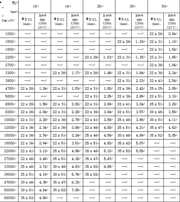
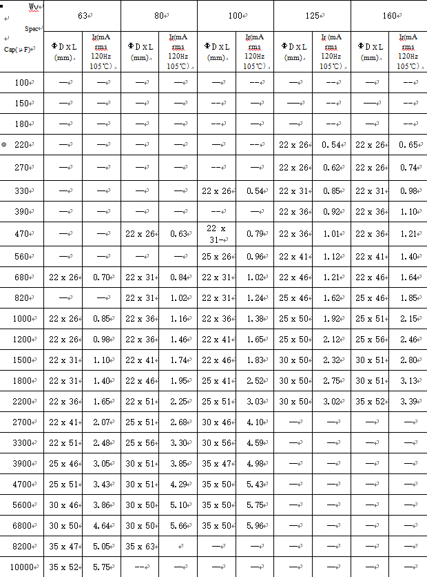
We offer different types of radial leaded capacitors customized ranging from 1000uf25v to 4700uf35v, customizing radial electrolytic capacitors to your requirements for all your applications.

Features:

Radial leaded electrolytic capacitors are high volume, small size, high reliability, long life, high reliability, stable capacity, good resistance to high temperature and humidity, etc.

Application scope:

Radial lead type aluminum electrolytic capacitors are widely used in electronic precision instruments. Various small electronic devices for resonance, coupling, filtering, bypass.


How to distinguish the positive and negative polarity of radial lead type capacitor?

Radial electrolytic capacitors are polarized, so it is important for them to have the polarity soldered correctly. If not, they will exhaust (bulge at the top) after a few minutes of operation.

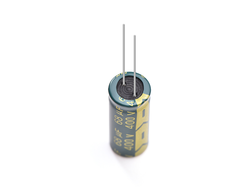
The positive and negative electrolytic capacitors are distinguished: the black block with the logo on top of the capacitor is the negative pole, there are two semicircles on the capacitor position on the PCB, the color painted semicircle corresponding to the pin is the negative pole, also the length of the pin is useful to distinguish the positive and negative polarity.

1、Bolt type electrolytic capacitor positive and negative identification. Bolt type aluminum electrolytic capacitors have clear positive and negative identification on the casing, positive pole is marked with "+" and negative pole is marked with "-". Most of the bolt type capacitors have "+" and "-" marks engraved next to the terminals on the cover.

2、Differentiation of positive and negative electrodes of solder lug aluminum electrolytic capacitors. Solder lug aluminum electrolytic capacitors are also called bullhorn capacitors, currently all manufacturers choose "negative pole marking", that is, the solder pin corresponding to the casing "-" mark is the negative pole. Most of them adopt "embossing" to identify the negative pole, and some electrolytic capacitor manufacturers directly print "+" and "-" on the rivet. logo.

3、Lead structure electrolytic capacitor positive and negative identification method. The lead structure electrolytic capacitor also adopts "negative pole identification", that is, the lead corresponding to the "-" mark of the casing is negative pole. There is also the identification by the length of the lead, the long lead is the positive pole, the short lead is the negative pole.

If you want to know more about electrolytic capacitors, please contact us.

Read More

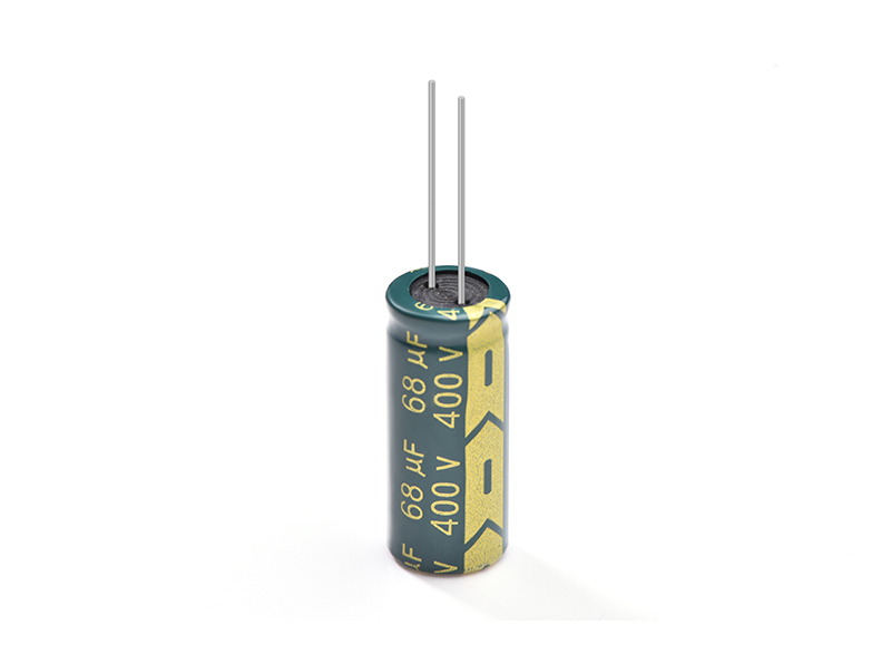
Home > Capacitors > Radial Leaded Capacitor > Electrolytic capacitor 68UF400V size13*30mm LOWESR DIP 105° For LED power supply

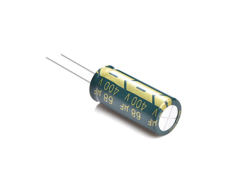
Electrolytic capacitor 68UF400V size13*30mm LOWESR DIP 105° For LED power supply

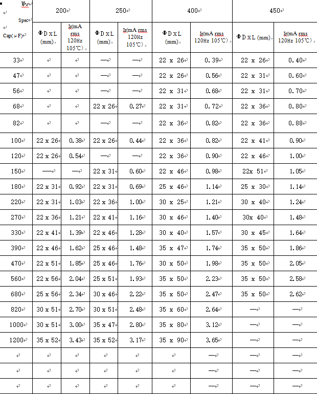
Electrolytic capacitor 68UF400V

SHDR® Application Notes

Reverse voltage causes short circuit breakage of the capacitor or leakage of electrolyte. Where the polarity in a circuit sometimes reversed or unknown, a bi-polar capacitor should be used.

When you use aluminum electrolytic capacitors, remember the following:

1. Polarity

Regular aluminum electrolytic capacitors has polarity

Reverse voltage causes short circuit breakage of the capacitor or leakage of electrolyte. Where the polarity in a circuit sometimes reversed or unknown, a bi-polar capacitor should be used.

2. Overvoltage

Do not apply overvoltage continuously.

When overvoltage is applied to the capacitor, leakage current increase drastically.

Applied working voltage to capacitors should not exceed the rated working voltage of capacitor.

3. Operating temperature and life

Do not use the capacitor over the max operating temperature.

Life time of the capacitor depends on the temperature.

Generally, life time is doubled by decreasing each temperature 10℃

Use temperature as low as possible.

4. Vent

It is recommended at least 3mm of space around the vent.

If such space is not provided, the vent will not operate completely.

5. Ripple current

Do not apply a ripple current exceeding the rated maximum ripple current.

Applying too much ripple current to the capacitor causes great heat generation, invites deterioration of properties of causes breakage.

Please consult factory if ripple current exceeds the specified limit.

6. Charge and discharging

Frequent and quick charge/discharge generates heat inside the capacitor, causing increase of leakage current, decrease of capacitor, or breakage occasionally.

Consult us for assistance in this application.

7. Storage

When the capacitor is stored for a long time without applying voltage, leakage current tends to increase.

This returns to normal by applying the rated voltage to the capacitor before use.

It is recommended to apply D.C. working voltage to the capacitor for 30 minutes through 1kΩ of protective series resistor, if it is stored for more than 6 mouths.

The capacitor should be stored at a normal temperature and humidity.

8. Soldering

Improper soldering may shrink or break the insulating sleeve add/or damage the internal element as terminals and Lead wires conduct heat into the capacitor.

Avoid too high a soldering temperature and/or too long a soldering time.

9. Mechanical stress on the lead wire and the terminal

Do not apply excessive force to the lead wire and the terminal.

Do not move the capacitor after soldering to the PC board, not carry the PC board by picking up the capacitor. For their strength, refer to JIS C-5141 and C-5102.

10. Cleaning of boards after soldering

If the capacitor is cleaned in halogenated solvent for organic removing solder flux solvent, the solvent may penetrate into inside of capacitor, and may generate corrosion.

11. Sleeve material

The standard sleeve material is polyvinyl-chloride.

If exposed to xylene, toluene, etc, and then subjected to high heat, the sleeve may crack. This sleeve is not insulating material.

12. Micon's Products meet or exceed quality standards specified by JIS-C5141W and with the reliability requirements refer to JIS-C-5102.


Capacitors

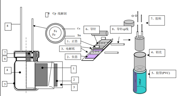
Capacitor structure detail diagram
Capacitor structure detail diagram


Capacitors


Capacitors


Capacitors

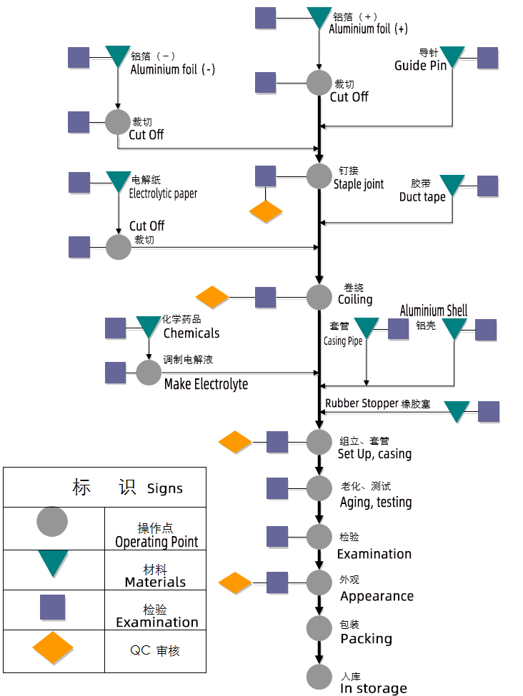
Capacitive process flow


1000uf 25v Capacitive process flow

For other custom capacitors you can contact us and we will give you a good price.

Product Picture
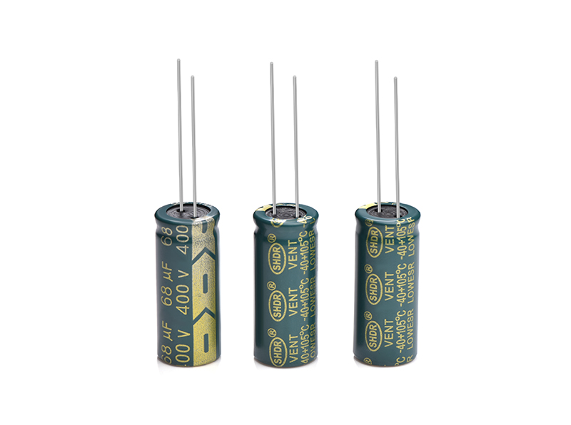


  • Electrolytic capacitor 68UF400V size13*30mm LOWESR DIP 105° For LED power supply

  • Electrolytic capacitor 68UF400V size13*30mm LOWESR DIP 105° For LED power supply

  • Electrolytic capacitor 68UF400V size13*30mm LOWESR DIP 105° For LED power supply

  • Electrolytic capacitor 68UF400V size13*30mm LOWESR DIP 105° For LED power supply

Related Products


Contact Us
  • +86 137 2340 5911
  • keven@shdrcap.com
  • No. 232, West Huifu road, Yuexiu district, Guangzhou City, Guangdong Province, China
Newsletter

Copyright © Guangzhou Shenghe Electronic Technology Co., Ltd. All Rights Reserved Sitemap | Powered by Reanod