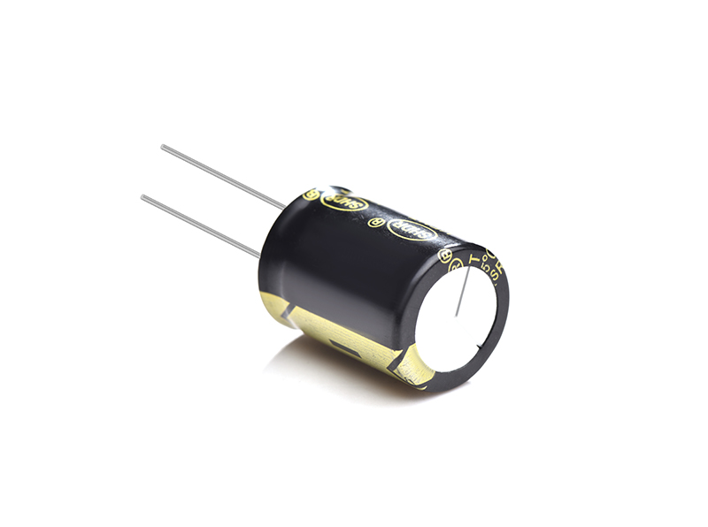
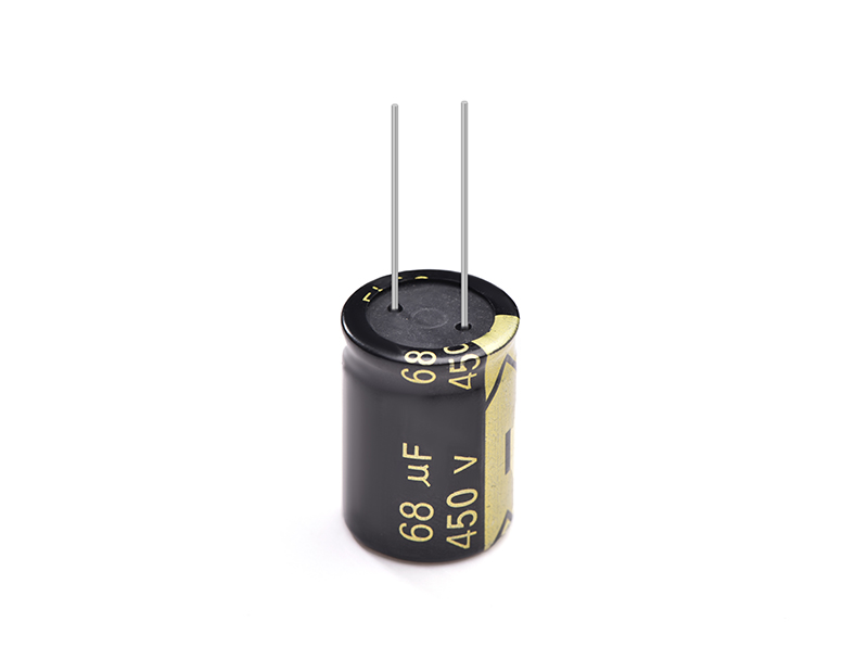
Electrolytic capacitor 68UF450V
SHDR® Application Notes
Caution DuringCircuitDesign
1. Please make sure the application and mounting Conditiorts to which the capacitor will be exposed are within the conditions specified in the catalog or alternate product specification (Referred as to
2. Design Aluminum Electrolytic Capacitors, please pay attentiontothe points listed below.
(1). The capacitor shall not be used in en ambient temperature which exceeds the operating temperature pacified in the specification.
(2). Do not apply excessive current which exceeds the allowableripple current .
(3). Make sure that no excess voltage (that is higher than the rated voltage)is applied to the capacitor.
(a). Please pay attention so that the peak voltage, which is DC voltage overlapped by ripple current,will not exceed the rated voltage.
(b). In the case where more than 2 aluminum electrolytic capacitors are used in series please make sure that applied voltage will be lowor than rated Volrage and the voltage
be will applied to each capacitor equally using a balancing resistor in parallel with the capadtors.
(4). Aluminum electroiytic capacitors are poiartzed. Make surethatno reversevoltage or AC voltage is applied to the capacitors. Please use Bi-polar capacitors for a circuit that can possibly see reversed polarity. Even Bi-polar capedtorcan not be USed for ac voltage application.
3. Appropriate capacitors which comply with the life requirement of the products should be selected when designing the circuit.
4. For a drcuit that repeats rapid charging discharging of electricity, an appropriate capacitor that is capable ofenduringsuch a condition must be used.
5. Aluminum case, cathode lead wire, anode lead wire and circuit pattern must be isolatad.
6. The sleeve of cepacitoreisnot recognized as an insulator, and therefore, the standard capacitor should not be uesd in a place where insulation function is needed. Please consult with us should you require a higher grade of insulating sleeve.
7. Capadtors may fail if they are used under the following conditions.
(1). Damp conditions such as water, saltwater spray, or oil spray or fumes. High humidity or humidity condensebon sttuations.
(2). In an atmosphere filled with toxic gasses (such as hydrogen sulfide, sulfurous acid, nitrous acid, chlorine. ammonia, etc. )
(3). Being exposed to direct sunlight, ozone, ultraviolet ray, or radiation.
(4). Being exposed to acidic or alkaline solutions
(5). Under severe conditions where vibration and/or mechanical shock exceed the applicable ranges of the specification.
8. In designing a circuit, the following matters should be ensured in advancetothe capacitor assemblyon the P.C. board.
(1). Design the appropriate hole spacing to match the lead pitch ofcapacitors
(2). Do not locate any wiring and clrcuit patterns dirsctly above the capacitor vent, Ensure enough free space above the capacitor vent.
(3). Do not design a circuit board so that heat generating components are placed near an aluminum electrolvtic capacitor Or reverse side of P.C. board (under the capacitor).
9. Electrical characteristics may vary depending on changes in temperature and frequency. Please consider this variation when you design drcuits.
10. When you mount capacitorson the double-sided P.C boards, do not place capecttors on circuit patterns oroveron unused holes.
11. When you install more than 2 capacitors in parallel, considerthe balance of current flowing through the capacitors.
12. If more than 2 aluminum electrolytic capacitors are used in seriesmake sure the applied voltage will be lower than the rated voltage and that voltage will be applied to each capacitor equally using balancing resistor in parallel witt each capacitor.
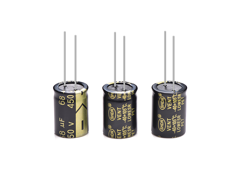
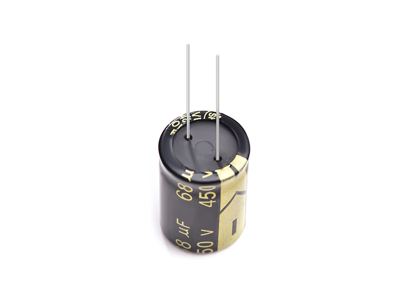
Product Picture
Copyright © Guangzhou Shenghe Electronic Technology Co., Ltd. All Rights Reserved Sitemap | Powered by
