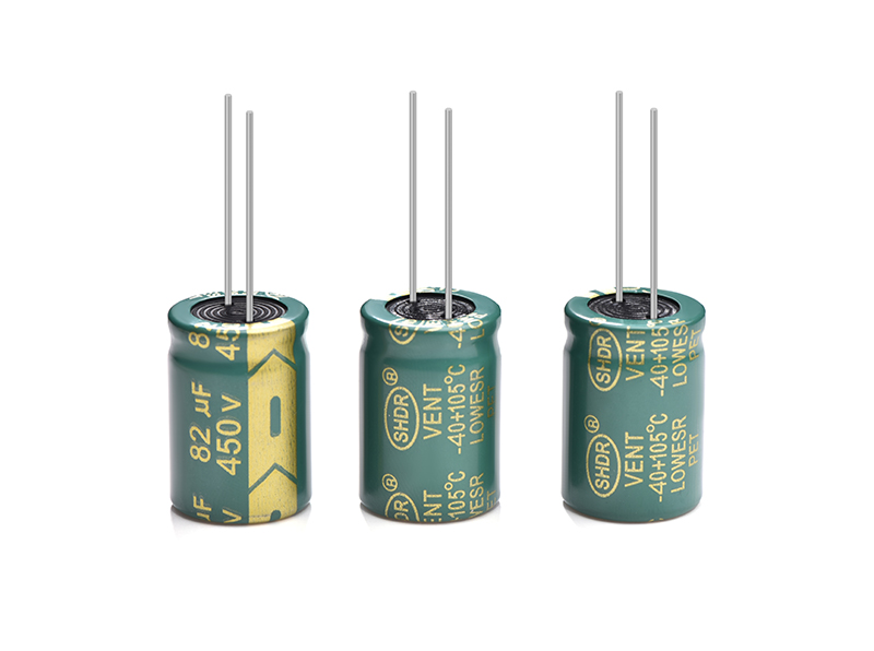
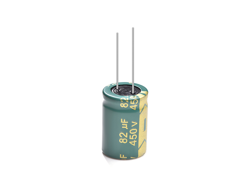
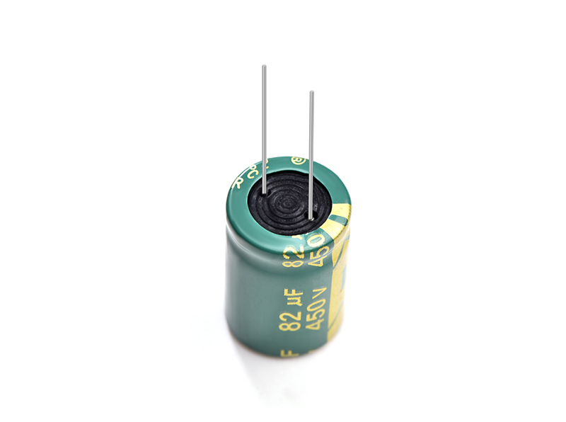
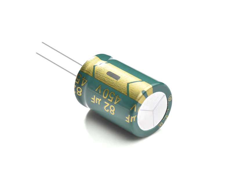
Electrolytic capacitor 82UF450V
SHDR® Application Notes
Caution For Assembling Capacitors
1. Once a capacitor has been assembled in the set and power applied, even if a capacitor is discharged, an electric potenlial (restricting voltage) may exist between the terminals.
2. Electric potential between positive and negative terminal may exist as a result of returned electromotive force, so please discharge the capacitor using 1KΩ resistor.
3. Leakage current of aluminum olocirolylic capacitors may be increased during long storage time. In this case, the capacitors should be subjoct to voltage treatment a 1KΩ resistor before use.
4. Please confirm ratirlgs (voltago and eapadtance) arid polarity before in stalling capacitors on the P.C. board.
5. Do not drop capacitors on the floors and damage. nor use a capacitors that was dropped.
6. Please confirm that lead spacing of the capacitor matches the hole spacing of the P.C.board prior to installation.
7. Please pay attenlion that the clinch force is not too strong when capacitors are places and fixed by an automatic insertion machine.
8. Soldering
(1). Soldering condition (temperature and times) must be confirmed to be within Saliencecon spesification.
(2). Soldering iron should never touch the capacitors body and do not capacitors body into melted solder.
(3). Please avoid contact between other components and tho aluminum capacitor.
(4). Please avoid having flux adhere to any portion except the terminal.
9. Aftor Soldering
(1). Do not bend or twist the capacitors body after soldering On P.C. board.
(2). Do not hit the capacitors and isolate capacitons from the P.C. boerd or other device when stacking P.C. boards in store.
10. Standard Aluminum Electrolytic Capacitors should be free from halogenated solvents during P.C board cleaning after soldering.
11. Do not use halogenated adhesives anti coating materials to fix aluminum electrolytic capacitors.
Product Picture
Copyright © Guangzhou Shenghe Electronic Technology Co., Ltd. All Rights Reserved Sitemap | Powered by
