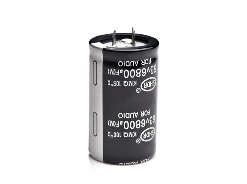
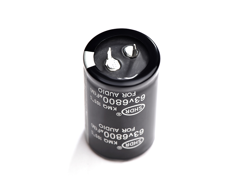
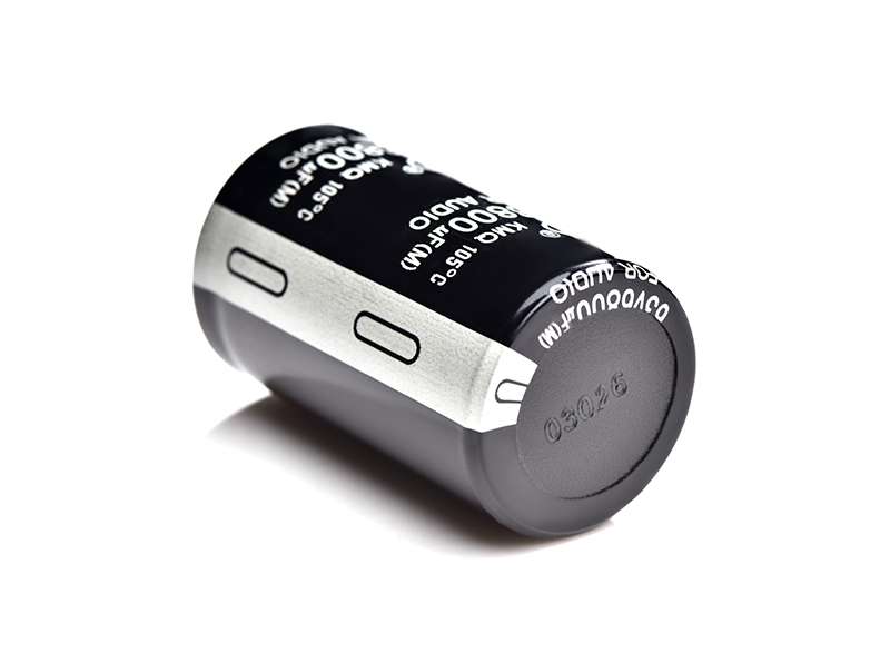
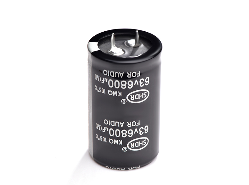
High Voltage Aluminium Electrolytic Capacitor
SHDR® Application Notes
1 Factors affecting the life of electrolytic capacitors
Electrolytic capacitors are widely used in different fields of power electronics, mainly for smoothing, energy storage or filtering after AC voltage rectification, and also for non-precise timing delays. When the MTBF of the switching power supply is estimated, the model analysis results show that the electrolytic capacitor is the main factor affecting the life of the switching power supply, so it is very important to understand and affect the factors affecting the life of the capacitor.
The life of an electrolytic capacitor depends on its internal temperature. Therefore, the design and application conditions of electrolytic capacitors will affect the life of electrolytic capacitors. From the design point of view, the design method, material and processing technology of electrolytic capacitors determine the life and stability of the capacitor. For the user, the use of voltage, ripple current, switching frequency, installation form, heat dissipation method, etc. all affect the life of electrolytic capacitors.
2 Abnormal failure of electrolytic capacitors
Some factors can cause electrolytic capacitors to fail, such as extremely low temperature, capacitor temperature rise (soldering temperature, ambient temperature, AC ripple), excessive voltage, transient voltage, very high frequency or reverse bias; where temperature rise is a The operating life (Lop) of electrolytic capacitors is the most influential factor.
The conductivity of the capacitor is determined by the ionization ability and viscosity of the electrolyte. As the temperature decreases, the viscosity of the electrolyte increases, and thus the ionic mobility and electrical conductivity decrease. When the electrolyte is frozen, the ion mobility is very low resulting in very high electrical resistance. On the contrary, excessive heat will accelerate the evaporation of the electrolyte, and when the amount of electrolyte is reduced to a certain limit, the life of the capacitor will be terminated. When working in alpine regions (generally below -25°C), heating is required to ensure the normal working temperature of the electrolytic capacitor. For example, outdoor UPS is equipped with heating plate in northeastern my country.
Capacitors are easily broken down under overvoltage conditions, and surge voltages and transient high voltages in practical applications often occur. In particular, my country has a vast territory and complex power grids in various places. Therefore, the AC power grid is very complicated, and often exceeds 30% of the normal voltage. Especially for single-phase input, the phase deviation will increase the normal range of AC input. The test shows that the commonly used 450V/470uF 105 ℃ imported ordinary 2000-hour electrolytic capacitor, under the voltage of 1.34 times the rated voltage, will leak liquid and gas after 2 hours, and the top will burst open. According to statistics and analysis, the failure of the PFC output electrolytic capacitor of the communication switching power supply close to the power grid is mainly due to power grid surge and high voltage damage. The voltage selection of electrolytic capacitors generally carries out two-level derating, and it is more reasonable to reduce the voltage to 80% of the rated value.
3 Analysis of factors affecting life expectancy
Except for abnormal failures, the life of electrolytic capacitors has an exponential relationship with temperature. Due to the use of non-solid electrolytes, the life of electrolytic capacitors also depends on the evaporation rate of the electrolyte, resulting in reduced electrical performance. These parameters include capacitance, leakage current and equivalent series resistance (ESR).
Refer to the formula of RIFA's estimated lifespan:
PLOSS = (IRMS)²xESR (1)
Th = Ta + PLOSS x Rth (2)
Lop = A x 2 Hours (3)
B = reference temperature value (typical value is 85 ℃)
A = Capacitor life at reference temperature (varies with capacitor diameter)
C = number of degrees of temperature rise required to reduce the life of the capacitor by half
From the above formula, we can clearly see that there are several direct factors that affect the life of electrolytic capacitors: ripple current (IRMS) and equivalent series resistance (ESR), ambient temperature (Ta), transfer from hot spots to surrounding The total thermal resistance (Rth) of the environment. The point with the highest temperature inside the capacitor is called the hot spot temperature (Th). The hot spot temperature value is the main factor affecting the working life of the capacitor. The following factors in turn determine the outside temperature (ambient temperature Ta) in the actual application of the hot spot temperature value, the total thermal resistance (Rth) transferred from the hot spot to the surrounding environment and the energy loss (PLOSS) caused by the alternating current. The internal temperature rise of the capacitor has a linear relationship with the energy loss.
When the capacitor is charged and discharged, the current will cause energy loss when flowing through the resistor. The voltage change will also cause energy loss when passing through the dielectric. In addition to the energy loss caused by leakage current, the result of all these losses is the internal temperature of the capacitor. rise.
3.1. Design considerations
In non-solid electrolyte capacitors, the dielectric is the oxide layer of the anode aluminum foil. The electrolyte acts as an electrical contact between the oxide layers of the cathode aluminum foil and the anode aluminum foil. The paper interlayer that absorbs the electrolyte becomes the isolation layer between the cathode aluminum foil and the anode aluminum foil, and the aluminum foil is connected to the terminal of the capacitor through the electrode lead tab.
By reducing the ESR value, the internal temperature rise caused by the ripple current in the capacitor can be reduced. This can be achieved by using multiple electrode lead tabs, laser welding electrodes, etc.
The ESR value and ripple current determine the temperature rise of the capacitor. One of the main measures to make the capacitor have a satisfactory ESR value is that one or more metal electrode leads are usually used to connect the external electrode and the core package to reduce the impedance between the core package and the pins. The more electrode tabs on the core package, the lower the ESR value of the capacitor. With the help of laser welding technology, more electrode tabs can be added to the core package, thus enabling the capacitor to achieve a lower ESR value. This also means that the capacitor can withstand higher ripple current and have lower internal temperature rise, which means longer operating life. Doing so is also beneficial to improve the ability of the capacitor to resist vibration, otherwise it may lead to internal short circuit, high leakage current, loss of capacitance, rise in ESR value and open circuit.
Through the good mechanical contact between the capacitor core package and the bottom of the aluminum shell and the heat sink in the middle of the core package, the internal heat of the capacitor can be effectively released from the bottom of the aluminum shell to the bottom plate connected to it.
The internal thermal conduction design is extremely important for the stability and working life of the capacitor. In Evox Rifa's design, the negative aluminum foil is extended to directly touch the thick bottom of the capacitor's aluminum case. This bottom becomes the heat sink of the core package, so that the heat of the hot spot can be released. If you choose to install with bolts, you can safely install the capacitor on the bottom plate (usually aluminum plate), you can get a more comprehensive thermal conduction solution with lower thermal resistance (Rth.).
· The loss of electrolyte can be greatly reduced by adopting a phenolic plastic cover with electrodes and a double special sealing gasket tightly engaged with the aluminum shell.
The evaporation of the electrolyte through the gasket determines the working time of the long-life electrolytic capacitor. When the capacitor's electrolyte evaporates to a certain extent, the capacitor will eventually fail (this result will be accelerated by the internal temperature rise). Evox Rifa's dual-layer sealing system slows down the evaporation of the electrolyte, allowing the capacitor to reach its maximum operating life.
These characteristics ensure that the capacitor has a long working life in the required field.
3.2. Application factors that affect life expectancy
According to the life formula, it can be concluded that the application factors affecting the life are: ripple current (IRMS), ambient temperature (Ta), and the total thermal resistance (Rth) transferred from the hot spot to the surrounding environment.
1. Ripple current
The magnitude of the ripple current directly affects the hot spot temperature inside the electrolytic capacitor. Check the user manual of electrolytic capacitors to get the allowable range of ripple current. If it exceeds the range, it can be solved in parallel.
2. Ambient temperature (Ta) and thermal resistance (Rth)
According to the formula of hot spot temperature, the application environment temperature of electrolytic capacitors is also an important factor. In application, environmental heat dissipation method, heat dissipation intensity, distance between electrolytic capacitor and heat source, installation method of electrolytic capacitor, etc. can be considered.
The heat inside the capacitor is always conducted from the "hot spot" with the highest temperature to the part where the surrounding temperature is relatively low. There are several ways of heat transfer: one is conduction through aluminum foil and electrolyte. If the capacitor is mounted on a heat sink, some of the heat will also be transferred to the environment through the heat sink. Different mounting styles and spacing and heat dissipation will affect the thermal resistance of the capacitor to ambient. The total thermal resistance from the "hot spot" to the surrounding environment is denoted by Rth. Using clip mounting, install the capacitor on a heat sink with a thermal resistance of 2°C/W, and the obtained thermal resistance value of the capacitor Rth = 3.6°C/W; using bolt mounting, install the capacitor on a thermal resistance of 2°C/W On the heat sink, when the forced air cooling rate is 2m/s, the obtained capacitor thermal resistance value Rth = 2.1℃/W. (Take PEH200OO427AM type capacitor as an example, the ambient temperature is 85℃).
In addition, it is also a good way to reduce the thermal resistance by directly contacting the extended cathode aluminum foil with the capacitor aluminum shell. At the same time, it should be noted that the aluminum shell will be negatively charged and cannot be connected to the negative electrode.
A capacitor must be installed correctly to achieve its designed operating life. For example: RIFA PEH169 series and PEH200 series should be installed vertically upwards or horizontally. At the same time, make sure that the safety valve is facing upwards, so that the hot electrolyte and vapor can be smoothly discharged from the safety valve when the capacitor fails.
When the capacitors are very compactly arranged, there should be at least a 5mm space between adjacent capacitors to ensure proper air flow. Nut torque control is very important when using bolted installations. If it is screwed too loosely, the capacitor and the heat sink will not be in close contact; if it is screwed too tightly, the threads may be damaged. At the same time, it should be noted that the capacitor should not be installed upside down, otherwise the bolts may be broken.
The capacitor should be installed as far away as possible from the heating element, otherwise the excessive temperature will shorten the service life of the capacitor, thus making the capacitor the component with the shortest life in the entire circuit. In the case of high ambient temperature, try to use forced air cooling and install the capacitor at the air inlet.
3. The effect of frequency
If the current is composed of fundamental frequency and multiple harmonics, the power loss value generated by each harmonic must be calculated, and the calculation results must be added to obtain the total loss value.
In high frequency applications, the leads at both ends of the capacitor should be as short as possible to reduce the equivalent inductance.
The resonant frequency (fR) of the capacitor varies depending on the type of capacitor. For solder-tab and bolt-on aluminum electrolytic capacitors, the resonant frequency is between 1.5kHz and 150kHz. If the capacitor is used above the resonant frequency, the external characteristics are inductive.
4 Conclusion
To sum up, in the case of avoiding abnormal failure, choosing the correct application conditions and environment, the life of electrolytic capacitors can be guaranteed.
Product Picture


Copyright © Guangzhou Shenghe Electronic Technology Co., Ltd. All Rights Reserved Sitemap | Powered by
